Design Guidelines: Plastic Injection Molding
Our basic guidelines for plastic injection molding include important design considerations to help improve part moldability, enhance cosmetic appearance, and reduce overall production time.
Size
Maximum Dimensions
| SIZE | 18.9 in. x 29.6 in. x 8 in. |
|---|---|
| VOLUME | 59 cu. in. |
| DEPTH | 4 in. from parting line |
| Up to 8 in. if parting line can pass through the middle of the part | |
| PROJECTED MOLD AREA | 175 sq. in. |
| SIZE | 480mm x 751mm |
|---|---|
| VOLUME | 966,837 cu. mm |
DEPTH |
101mm from parting line |
| Up to 203.2mm if the parting line can pass through the middle of the part | |
| PROJECTED MOLD AREA | 112,903 sq. mm |
Typically, Protolabs can maintain a machining tolerance of +/- 0.003 in. (0.08mm) with an included resin tolerance that can be greater than but no less than +/- 0.002 in./in. (0.002mm/mm).

Materials
- ABS
- ABS/PC
- Acetal
- Acetal Copolymer
- Acetal Homopolymer
- ETPU
- HDPE
- LCP
- LDPE
- LLDPE
- Nylon 6
- Nylon 5/12
- PBT
- PC/PBT
- PEEK
- PEI
- PET
- PETG
- PMMA
- Polycarbonate
- Polypropylene
- PPA
- PPE/PS
- PS
Surface Finishes
| FINISH | DESCRIPTION |
|---|---|
| PM-F0 | non-cosmetic, finish to Protolabs' discretion |
| PM-F1 | low-cosmetic, most toolmarks removed |
| PM-F2 | non-cosmetic, EDM容许 |
| SPI-C1 | 600 grit stone, 10-12 Ra |
| PM-T1 | SPI-C1 + light bead blast |
| PM-T2 | SPI-C1 + medium bead blast |
| SPI-B1 | 600 grit paper, 2-3 Ra |
| SPI-A2 | grade #2 diamond buff, 1-2 Ra |
Mold texturingapplies industry standard textures to a mold and you can expect the equivalent of a Mold-Tech finish.
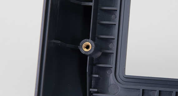
Threaded insertsare possible through secondary heat staking and ultrasonic welding processes. A complete chart ofstocked inserts is available here.
Pad printingtransfers a two-dimensional image like company logos onto a three-dimensional object.
Laser engravingis applied to the mold or directly to final parts for information such as part numbers.
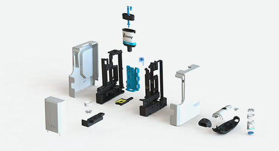
Basic assemblyincludes fastening molded parts together that we’ve manufactured and/or applying of labels to individually bagged parts.
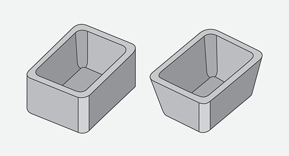
Draft
| VERTICAL FACES |
0.5° |
|---|---|
| MOST SITUATIONS |
2° |
| MINIMUM FOR SHUT OFF | 3° |
| 最小光TEXTURE (PM-T1) | 3° |
| 最小光TEXTURE (PM-T2) | 5°+ |
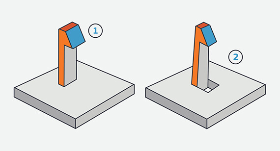
Undercuts
Maximum Side Core Dimensions
| WIDTH | HEIGHT | PULL |
|---|---|---|
| <8.419 in. | <2.377 in. | <2.875 in. |
Maximum Side Core Dimensions
| WIDTH | HEIGHT | PULL |
|---|---|---|
| <213.84mm | <60.38mm | <73.66mm |
Wall Thickness
| MATERIAL | RECOMMENDED WALL THICKNESS |
|---|---|
| ABS | 0.045 in. - 0.140 in. |
| Acetal | 0.030 in. - 0.120 in. |
| Acrylic | 0.025 in. - 0.500 in. |
| Liquid Crystal Polymer | 0.030 in. - 0.120 in. |
| Long-Fiber Reinforced Plastics | 0.075 in. - 1.000 in. |
| Nylon | 0.030 in. - 0.115 in. |
| Polycarbonate | 0.040 in. - 0.150 in. |
| Polyester | 0.025 in. - 0.125 in. |
| Polyethylene | 0.030 in. - 0.200 in. |
| Polyphenylene Sulfide | 0.020 in. - 0.180 in. |
| Polypropylene | 0.035 in. - 0.150 in. |
| Polystyrene | 0.035 in. - 0.150 in. |
| Polyurethane | 0.080 in. - 0.750 in. |
Table is adapted frommanufacturingcenter.com.
| MATERIAL | RECOMMENDED WALL THICKNESS |
|---|---|
ABS |
1.143mm - 3.556mm |
| Acetal | 0.762mm - 3.048mm |
| Acrylic | 0.635mm - 12.7mm |
| Liquid Crystal Polymer | 0.762mm - 3.048mm |
| Long-Fiber Reinforced Plastics | 1.905mm - 25.4mm |
| Nylon | 0.762mm - 2.921mm |
| Polycarbonate | 1.016mm - 3.81mm |
| Polyester | 0.635mm - 3.175mm |
| Polyethylene | 0.762mm - 5.08mm |
| Polyphenylene Sulfide | 0.508mm - 4.572mm |
| Polypropylene | 0.889mm - 3.81mm |
| Polystynene | 0.889mm - 3.81mm |
| Polyurethane | 2.032mm - 19.05mm |
Table is adapted frommanufacturingcetner.com.
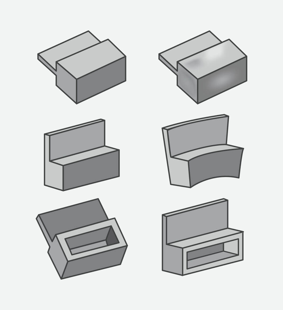
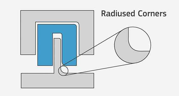
Radii
Some part corners will have a radius rather than a sharp edge since we use an automated CNC milling process to make the mold for your parts. This typically does not require a change to your model, but resulting radii are identified before the mold is milled.